Applications:
|
|
Features:
|
|
DescriptionThe PRL-454T-SMA is a 1:4 digital signal fanout buffer and level translator with one TTL input and four LVDS outputs. The TTL input has a 1 kΩ or 50 Ω input impedance, selectable by a toggle switch. The 1 kΩ input setting is used most often for receiving signals from digital I/O boards. These DIO boards are generally not designed for driving 50 Ω loads. For this type of application, it is recommended that the interconnecting cable length be limited to no more than 18 inches. For applications exceeding this length, pre-buffering the TTL signal with a PRL-444, High Input Impedance Line Driver, may be required. When switched to the 50 Ω input position, fmax can be increased beyond 400 MHz. Since very few affordable TTL clock generators can run beyond 250 MHz, we recommend that the PRL-177A-500 be used for testing the PRL-454T-SMA. The PRL-454T-SMA has a 5 V tolerant input and can be driven by the PRL-177A-500 directly. The PRL-454T-SMA is supplied with a PRL-760E ±9.0 V/1.8 A AC/DC adapter and housed in a 1.3 x 2.9 x 2.9-in. extruded aluminum enclosure. The PRL-454T-SMA may also be ordered without the power supply as part number PRL-454T-SMA-OEM. A maximum of four units can share the included PRL-760E AC/DC adapter using additional units of cable #88000102-4. If mounting is desired, a pair of the #35001420 mounting brackets can accommodate any two PRL modules of the same length. |
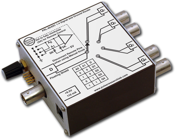
 Fig. 1: PRL-454T Block Diagram
(0° C ≤ TA ≤ 35° C)*
| SYMBOL | PARAMETER | Min | Typ | Max | UNIT | Comment |
|---|---|---|---|---|---|---|
| RIN1 | Input Resistance Low Range | 49.5 | 50.0 | 50.5 | Ω | |
| RIN2 | Input Resistance High Range | 990 | 1000 | 1010 | Ω | |
| ROUT | Output Resistance (current source) | N/A | ||||
| VIL | TTL Input Low Level | -0.5 | 0.0 | 0.8 | V | |
| VIH | TTL Input High Level | 1.6 | 2.0 | 5.0 | ||
| VOL | LVDS Output Low Level | 1.05 | V | |||
| VOH | LVDS Output High Level | 1.35 | V | |||
| VCMO | Output Common mode voltage1 | 1.20 | V | |||
| IDC | DC Input Current | 150 | mA | |||
| VDC | DC Input Voltage | 7.5 | 8.5 | 12.0 | V | |
| VAC1 | AC/DC Adapter Input Voltage, 120 | 103 | 115 | 127 | V | |
| VAC2 | AC/DC Adapter Input Voltage, 220 | 206 | 220 | 254 | V | |
| tPLH | Propagation Delay to output ↑ | 2.7 | ns | |||
| tPHL | Propagation Delay to output ↓ | 2.7 | ns | |||
| tr/tf | Rise/Fall Times (10%-90%) | 500 | 700 | ps | ||
| tSKEW | Skew between any 2 outputs | 300 | 550 | ps | ||
| fMAX1 | Max Clock Frequency, RIN = 50 Ω | 350 | 400 | MHz | ||
| fMAX2 | Max Clock Frequency, RIN = 1k Ω | 200 | 250 | MHz | ||
| Size | 1.3 x 2.9 x 2.9 | in | ||||
| Weight | 5 | Oz | ||||
| Shipping Weight | 4 | lbs | ||||
Notes:
- VCMO = (VOH+VOL)/2
- Rise and Fall times are measured using a PRL‑425NCML LVDS receiver and a PRL-860D-SMA inline signal monitor
- fMAX is measured using the PRL-177A-500 as the driver and the PRL-425NCML as the as the receiver.