Signal Conditioning Kits

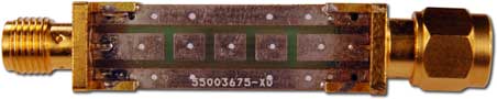
Closeup of PRL-MNET-BMF populated as an 80 dB attenuator
Applications:
- DC Blocks
- Feed-through 50 Ω Termination
- Custom Attenuators
- Multi-Pole Filters
- Series Resistor, Inductor or R-L Network
- Feed-through Decoupling Capacitor
- Schottky Diode Line Terminator
- Diode Detector
- In Line Amplifier*
- Diode Recovery Test Fixture*
- Transistor Switching Test Fixture*
* w/optional Bias Tee
Features:
- π-Network, T-Network, or Multi-Pole Filter Footprint on Both Sides of PCB
- Ground Plane and 50 Ω Transmission Line For Up To 5 GHz Bandwidth (SMA π model)
- Accepts #1206 and #0805 size SMT Components
- Populate With 1 to 28 Series or Shunt Components
- Accepts Mini-Circuits™ HFCN-2700 Series Filters ( BNC π and T models only)
- SMA or BNC Male/Female or Female/Female Connector Styles
- Metal Enclosure Included for Shielding
- 15 mm OD x 67.5 mm or 78 mm Length (BNC style)
- 0.44" W x 0.37" H outside dimension, 1.50" or 2.06" L Modules (SMA style)
Attention:
As of 11/10/23, PRL is suspending shipment of Signal Conditioning Conditioning Kits with BNC Male connectors, e.g. PRL-PINET-BMF, PRL-TNET-BMF, and PRL-MNET-BMF, pending resolution of a supply chain issue. All other connector options are still shipping, and we plan to resume shipments of the -BMF variants as soon as the supply chain issue is resolved. A -BFF configuration can be used in conjunction with a BNC Male-Male adapter (P/N 38005012) to create the equivalent of a -BMF configuration. We apologize for the inconvenience.
Description:
PRL's Signal Conditioning Kits enable quick and easy fabrication of custom signal-conditioning circuits for RF and high-frequency digital signals. SMA models run up to 5 GHz, and BNC models run up to 3 GHz.
Applications include attenuators, filters, DC blocks, feed-thru 50 Ω terminations, etc. They can be used to build commonly-used circuits, such as a 50 Ω shunt termination, or to build one-of a-kind fixtures not commercially available. Three PCB designs (π, T and multi-pole) enable easy construction of nearly any series and or parallel network. The double-sided footprint (identical on both sides of the PCB) allows non-standard resistor, inductor, and capacitor values to be fabricated easily and economically. With the addition of a Bias Tee, active device test fixtures can be built as well.
In one example, we easily fabricated a 24 dB attenuator with non-standard impedance for the interface between a vacuum tube output and a TTL input circuit, using a two-stage design with discrete SMT resistors. In another example, we level-shifted a -6V to +10V pulse to 0V to +16V for driving a high impedance circuit. In this case, we constructed a simple DC Restorer using a coupling capacitor and a shunt Schottky diode to ground.
Other examples include a feed-through decoupling capacitor, using one shunt capacitor to make an ideal low pass filter for noise reduction at I/O ports. The kits can be populated with as few as one series component, or as many as 28 series and shunt components, enabling a wide range of applications.
Five available connector styles (BNC M/F, BNC F/F, SMA M/F, SMA F/F, and SMA M/M) and a low-profile design enable inline insertion into your transmission line, with or without cables. Male/male styles are available for the SMA π and T configurations only. A gender changer may be used to create a M/M style for other configurations.
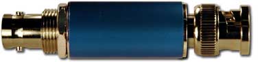
For BNC models a metal tube enclosure provides protection and shielding. A toothed washer and nut secure the enclosure and provide DC contact. For SMA models an extruded rectangular enclosure is provided. The enclosure makes contact by friction, and can be secured with a cyanoacrylate adhesive (Superglue) or epoxy. Contact conductance ensures DC connectivity, and the capacitive coupling between the SMA body and enclosure provides AC connectivity.
Products enlarged to show detail, and are not to scale. Vias are plated through to an identical pattern on the reverse side. Diagrams showing all possible component positions are available here.
| PCB | Connector Style |
BNC Picture/Part Number | SMA Picture/Part Number |
|---|---|---|---|
| π Network | Male/ Female |
|
|
| Female/ Female |
|
|
|
| Male/ Male |
|
|
|
| T Network | Male/ Female |
|
|
| Female/ Female |
|
|
|
| Male/ Male |
|
|
|
| Multi-Pole Network |
Male/ Female |
|
|
| Female/ Female |
|
|


| PCB Configuration | BNC Picture with Tube Cover Installed | SMA Picture with Cover Installed |
|---|---|---|
| π- Network or T-Network PCB |
|
|
|
||
|
||
| Multi-pole PCB |
|
 52 mm Length for SMA M/F |
|


Signal Conditioning Kits | Diagrams | Applications | Specifications | Datasheet
Component Positions
Diagrams show all possible component positions on both sides of PCB. Unpopulated series positions may require 0 Ω jumpers. This page may also be printed out and used as a worksheet. Schematics of sample applications are available here.

Fig 1a: π Network Component Positions |

Fig 1b: T Network Component Positions |

Fig 1c: Multi-pole Network Component Positions |
Signal Conditioning Kits | Detail | Applications | Specifications | Datasheet
Sample Applications and Calculators
Schematics:
Diagrams show only the component positions used in the specified circuit. Unpopulated series positions may require 0 Ω jumpers. Diagrams showing all possible component positions are available here. Component values calculators are available here.
| Application | Schematic | Kit Type | ||
|---|---|---|---|---|
| Pi | Tee | Multi | ||
| DC Block/Coupling Cap |  |
Y | Y | Y |
| AC Block/RF Choke |  |
Y | Y | Y |
| Series Termination |  |
Y | Y | Y |
| Shunt Termination |  |
Y | Y | Y |
| Precision Shunt Termination |  |
Y | Y | Y |
| Feed-through Decoupling Cap |  |
Y | Y | Y |
| Diode Detector |  |
Y | Y | Y |
| Attenuator |  |
Y | Y | Y |
| Low-pass Filter |  |
N | Y | Y |
| High-pass Filter |  |
N | Y | Y |
Online Filter and Attenuator Calculators:
-
Bandpass Filter Calculator by Raltron
-
High-pass/Low-pass/Bandpass/Bandstop/Notch Filter Calculator by Dale Heatherington, with frequency plots
-
L-C Filter Tutorial and Calculator by the late Prof. Tony Fisher (non-profit use only)
-
Pi/T Attenuator Calculator and Equations by RFCafe.com
-
Minimum-Loss Attenuator Calculator by Ernie Kim
These calculators will provide schematics and ideal component values for a variety of filter types (e.g. Butterworth, Chebyshev/Tchebysheff, Bessel) and attenuator configurations. Some will also provide response curves.
To implement the desired design with standard components, it may be necessary to use multiple component values in series or parallel configurations to approximate the calculated values. For example, the design for a 6 dB 50 Ω attenuator calls for a 37.4 Ω resistor, a value that is not commonly available. The attenuator can instead be built with two 75 Ω resistors in parallel, producing a very good 6 dB attenuator from standard components:
 |
 |
| "Ideal" 6 dB Attenuator Design | Actual 6 dB Attenuator Implementation |
A more complete Attenuator Application Note describes these techniques in more detail, including examples of many commonly-required attenuation ratios, measured performance, and oscilloscope captures.
Signal Conditioning Kits | Detail | Diagrams | Specifications | Datasheet
(0° C ≤ TA ≤ 35° C)*
BNC Kits
| Parameter | π Network | T Network | Multi-pole |
|---|---|---|---|
| Maximum series components | 2 | 4 | 8 |
| Maximum shunt components | 8 | 12 | 20 |
| Length, including BNC connectors | 68 mm/2.7 in | 68 mm/2.7 in | 78 mm/3.1 in |
| Diameter, including hex nut for cover | 16 mm/0.6 in | 16 mm/0.6 in | 16 mm/0.6 in |
SMA Kits
| Parameter | π Network | T Network | Multi-pole |
|---|---|---|---|
| Maximum series components | 2 | 4 | 8 |
| Maximum shunt components | 8 | 12 | 20 |
| Length, including SMA M/F connectors | 38 mm/1.5" | 52 mm/2.1" | |
| Length, including SMA F/F connectors | 35 mm/1.4" | 49 mm/2.0" | |
| Length, including SMA M/M connectors | 41 mm/1.6" | N/A | |
| Cross-section (W x H), including cover | 11.18 mm x 9.40 mm/0.44" x 0.37" | ||
Signal Conditioning Kits | Detail | Diagrams | Applications | Datasheet
| Qty. | Item | Description | Price |
|---|