Applications:
|
|
Features:
|
|
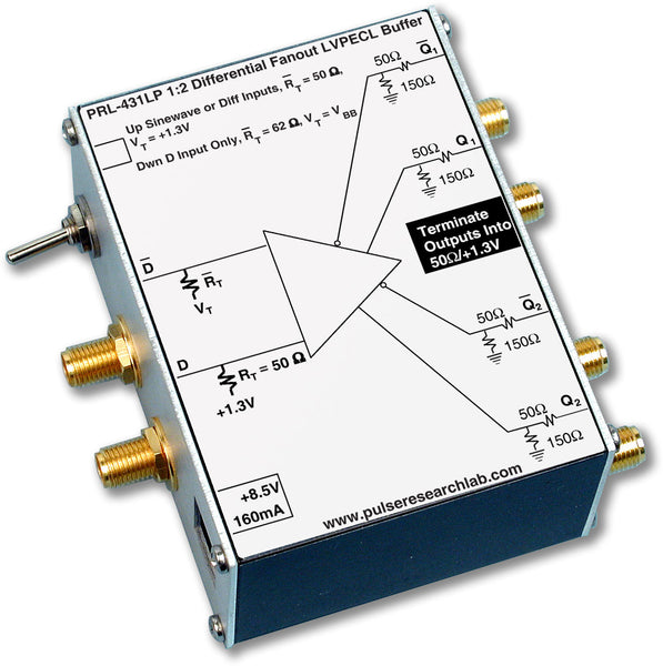
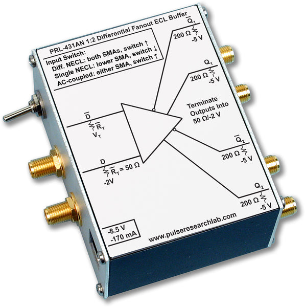
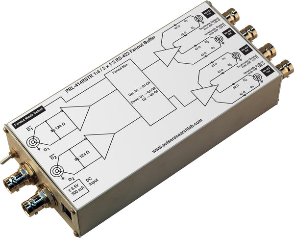
DescriptionThe PRL-454LV is a 1:4 LVDS fanout buffer and line driver. The floating 100 Ω universal differential input will receive LVDS, LVPECL*, NCML, or RS422 inputs with at least 300 mVPP differential input swing. Therefore the PRL-454LV can also be used to translate many different differential signal types to LVDS. The four pairs of complementary outputs are designed for driving floating 100 Ω loads, normally the configuration used in LVDS input circuits. The differential output swing is typically 300 mV with a common mode voltage of 1.0. All output connectors are SMA. The simple power supply requirements, +8 to +12 VDC/150 mA, allow the PRL-454LV to be used in many low power, portable applications in the field as well as in the lab. The PRL-454LV-SMA is supplied with a ±8.5 V/1.8 A AC/DC adapter and housed in a 1.3 x 2.9 x 2.9-in. extruded aluminum enclosure. The PRL-454LV-SMA may also be ordered without the power supply as part number PRL-454LV-SMA-OEM. A maximum of four units can share the included PRL-760E AC/DC adapter using additional units of cable #88000102-4. If mounting is desired, a pair of the #35001420 mounting brackets can accommodate any two PRL modules of the same length. *LVPECL drivers must have internal pull-down resistors to drive the floating load of the PRL-454LV. For translating LVPECL signals that lack internal pull-downs, use PRL-426LP, 2 Ch. LVPECL to LVDS Translator, with VTT/1.3 V LVPECL input terminations. |

(0° C ≤ TA ≤ 35° C)*
| SYMBOL | PARAMETER | Min | Typ | Max | UNIT | Comment |
|---|---|---|---|---|---|---|
| RIN | Input Resistance | 99 | 100 | 101 | Ω | |
| RINC | Common Mode Input Resistance | 5k | Ω | |||
| ROUT | Output Resistance (Current source) | NA | Ω | |||
| VIN | Input Voltage Range | -0.5 | +3.3 | V | ||
| VOL | Output Low Level | 1.05 | V | |||
| VOH | Output High Level | 1.35 | V | |||
| VCMO | Output Common mode voltage1 | 1.20 | V | |||
| IDC | DC Input Current | 150 | mA | |||
| VDC | DC Input Voltage | 7.5 | 8.5 | 12.0 | V | |
| VAC120 | AC/DC Adapter Input Voltage, 120 | 103 | 115 | 127 | V | |
| VAC220 | AC/DC Adapter Input Voltage, 220 | 206 | 220 | 254 | V | |
| tPLH | Propagation Delay to output ↑ | 2.7 | ns | |||
| tPHL | Propagation Delay to output ↓ | 2.7 | ns | |||
| tr/tf | Rise/Fall Times (10%-90%)2 | 500 | 700 | ps | ||
| tSKEW | Skew between any 2 outputs | 350 | 550 | ps | ||
| fMAX | Max Clock Frequency | 350 | 400 | MHz | ||
| Size | 1.3 x 2.9 x 2.9 | in. | ||||
| Weight | 5 | Oz | ||||
| Shipping Weight | 4 | lb | ||||
Notes:
- VCMO = (VOH+VOL)/2
- Rise and Fall times are measured using a PRL‑425NCML LVDS receiver and a PRL-860D-SMA inline signal monitor
- fMAX is measured using the PRL-177A-500 as the driver and the PRL-425NCML as the as the receiver.