FEATURES
- USB connectivity
- 37 I/O pins, individually configurable
- 3 ID pins
- C++ and LabVIEW support for Win32 and Win64
APPLICATIONS
- Control of switches, scanners, and logic gates from Pulse Research Lab or other manufacturers
- Trigger generation/detection
- Generic low-speed digital I/O
- System integration
The PRL-USBIO-1 module provides Windows-based USB control of PRL switches, scanners, and logic gates via USB. The module can also be used to control 3rd-party equipment and/or to provide or detect external triggers.
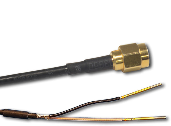
Each of 4 ports A, B, C, and E contains 8 pairs of signal/ground pins, Bits 0-7. Each port may be configured for input or output.
For Port D only, the 3 uppermost bits are reserved for the module ID (000 - 111 binary, corresponding to 0 - 7 decimal). The ID pins are pulled up internally, for a default ID of 111 = 7, and can be pulled down by grounding one or more pins with standard jumpers. A TTL-compatible High input (>2.0 V) will result in a value of 1.
The remaining 5 bits for Port D, D0 - D4, are available for I/O.
When configured as outputs, each signal pin will be shorted to GND or will output a nominal 5 V signal, depending on the 5-bit or 8-bit value written to the corresponding port.
When configured as inputs, each port will read a 5-bit or 8-bit value, depending on whether the signal pins read a TTL 0 (< 0.8 V, nominal ) or a TTL 1 (> 2.0 V, nominal) at their inputs.
Ports A - D are connected to a pair of MCP23S17 serial port expanders which can source or sink 25 mA per pin, with the absolute maximum on VDD not exceed 125 mA and on VSS not to exceed 150 mA per expander device. Ports A and B share one MCP23S17 device, and Ports C and D share another MCP23S17 device, so each device can handle the rated current on VDD and VSS.
For example, 3 pins on each device can source a full 25 ma each and 4 pins on each device could sink 25 ma each and stay within absolute maximums.
Port E is driven directly off the Microchip PIC18F2550 CPU, and current on those pins varies by pin, but typically 8 - 10 mA. All of the port pins have a 5.1 Ω series resistor.
Power is supplied via USB.
LabVIEW and C++ software examples, with source code, are provided as:
- You will need install our PRLIO package, which includes a C++ app (with source) and the USB driver:
- For Windows 7/8/10, 32 or 64-bit.
- Your browser may take up to 60 seconds to begin the download. This is normal.
- Google Drive will warn that the file can't be scanned for malware. This is normal.
- Be sure to install both the application files and the drivers (selected by default)
- A set of rudimentary LabVIEW applications is included:
- Ensure that Source Code is checked when installing the PRLIO package as described above.
- If you don't have the full LabVIEW development environment installed you can run the .exe by installing the LabVIEW runtime engine:
- For Windows 7/64-bit.
- Tested only with 64-bit, for now
- If you have the full LabVIEW installed you can run and edit the .vi and the sub-vis.
- Version 2017 or later. Contact us if you need them down-saved for an older version.
- Known issues:
- The LV application is clumsy for controlling two USB devices simultaneously, unless you're programming them both similarly, because the LV application does not "read back" the configuration of the newly-selected device when the Device ID is changed, so you have to keep re-entering the settings for different modules.
- Presently the LV app configures, reads, and writes all ports on the selected ID, and there's no option to program only a subset of them.
Diagram

Applications
Specifications
| SYMBOL | PARAMETER | Min | Typ | Max | UNIT | Comments | |
|---|---|---|---|---|---|---|---|
| I/O Pin Spacing | 0.10 | in. | 0.025” square post header pins | ||||
| USB Receptacle | Type-B plug | ||||||
| USB Standard | USB 1.1 | ||||||
| VIH | Voltage Input Threshold, High | 2.0 | V | Configured for input | |||
| VIL | Voltage Input Threshold, Low | 0.8 | V | Configured for input | |||
| VOH | Voltage Output, High | 5 | V | Into 1 MΩ | |||
| VOL | Voltage Output, Low | 0 | V | Into 1 MΩ | |||
| IMAX1 | Max current/pin, ports A-D | 25 | mA | Limited to +125/-150 mA per expander | |||
| IMAX2 | Max current/pin, port E | 8 | mA | ||||
| L | Length | 3.60 | in. | Including connectors | |||
| W | Width | 2.90 | in. | ||||
| H | Height | 1.31 | in. | ||||
| Weight | 4.3 | Oz. | |||||