Single-Ended Impedance and Performance of Ethernet Cabling and the PRL-RJ45-SMA Adapter
Introduction and Motivation:
Pulse Research Lab conducted a series of experiments to evaluate the performance of various types of off-the-shelf Ethernet patch cables for carrying single-ended signals normally used in a 50 Ω environment.
A previous study evaluated the performance of the PRL-RJ45-SMA adapter and Cat 6a cables with signals in a nominal 100 Ω differential impedance environment; this follow-up expands the study to include single-ended signals, single-ended impedance measurements, and a comparison of different grades of Ethernet patch cables.
While the nominal differential impedance of the twisted pairs in Cat5e/Cat6a/Cat7 Ethernet patch cables is specified at 100 Ω1 , the single-ended impedance of a pair typically is not specified with respect to Ground for single-ended signals.
Because several of our customers have used the PRL-RJ45-SMA to adapt a set of 50 Ω SMA connections to RJ45 for single-ended signals, we wanted to measure the single-ended impedance of common Ethernet cables as well as transmit some high-speed single-ended signals through them.
As with the differential study done previously, we used basic reflectometry to perform impedance measurements.
Impedance Measurement via Reflectometry:
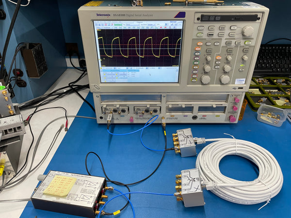
We began with the standard TDR pulse from a Tek 80E04 sampling head, installed in a Tektronix DSA8300 Sampling Scope. To establish a baseline we connected a length of 50 Ω coaxial cable to the sampling head. Ch. 1 shows the TDR pulse reflecting from the open circuit at the end of the cable and doubling the energy presented to the scope in the form of a “step” in the waveform:
 |
 |
|
TDR→50 Ω coaxial cable |
|
The first step above Ground is the Incident Wave, and the second step is the Reflected Wave. The length of the trace between the steps represents the double propagation delay through the cable, and the height of the second step above the first step represents the reflected energy:
The reflection coefficient, ρ (rho), is calculated by the following formula2:
where Z0 is the characteristic impedance, and ZL is the load impedance. We can then solve for ZL as follows:
With the cable “terminated” into an open circuit (e.g. no termination), VReflected = VIncident, so ρ = 250 mV/250 mV = 1, and ZL = ∞, as expected for an open circuit.
Now we introduce the PRL-RJ45-SMA adapter at the end of the cable, along with a 10’ length of Cat7 Ethernet patch cable. The PRL-RJ45-SMA adapter connects the TDR pulse on SMA Q1 to RJ45 Pin 7 (+BI_DD, the Brown/White wire in standard EIA/TIA 568B cabling for Gigabit Ethernet). All other connectors are tied to GND via SMA 0 Ω terminations.
 |
 |
|
TDR→Coax→PRL-RJ45-SMA→Cat7 cable, 10’ |
|
Now there is a small, additional step as the wave propagates through the 50 Ω impedance of the coax cable, though the PRL-RJ45-SMA adapter, and through the twisted pair inside the Cat7 cable bundle before hitting the open circuit. The height of the 2nd step, VReflected = ~10 mV, so ρ = ~0.04, and ZL = ~54 Ω for the segment of Cat7 cable.
54 Ω is a reasonably close to 50 Ω, and an acceptable substitute in all but the most demanding of applications, as single-ended signaling (e.g. TTL/CMOS) seldom exceeds 100 MHz in most board-to-board, box-to-box, or rack-to-rack applications where cabling is used. At higher data rates and/or over very long distances, differential signaling is recommended.
There is a visible impedance discontinuity through the PRL-RJ45-SMA adapter, as shown by the ripples in the waveform at the first step, but as will be shown in later scope captures, it does not significantly affect the delivered signal integrity.
We selected Cat7 cabling because it is double-shielded. There is a foil shield around each individual pair in the bundle, as well as an overall foil shield around the bundle, and all the shields are tied to the shield on the RJ45 plug. This plug makes a connection to the shielded RJ45 jack on the PRL-RJ45-SMA adapter assembly, which is also tied to the SMA shields and to case ground on the adapter assembly, providing a continuous, grounded shield throughout.
Comparison of Ethernet Cable Types:
As an experiment, we also measured the impedance of Cat6a cabling (outer foil shield, but no per-pair shield), and Cat5e cabling (no shield).
 |
|
Cat7 (white) vs. Cat6a (black) vs. Cat5e (blue) |
A comparison of the cable construction can be seen above.
First we swapped the 10’ Cat7 cable for a 3’ Cat7 cable, then added a shielded RJ45 coupler and a 3’ length of Cat6a cable:
 |
 |
|
TDR→Coax→PRL-RJ45-SMA→Cat7→Cat6a |
|
The new “step” height, VReflected = ~39 mV, so ρ = ~0.156, and ZL = ~68 Ω. This would not be a good substitute for 50 Ω coax cable
Finally we added another coupler and a length of Cat5e cable:
 |
 |
|
TDR→Coax→PRL-RJ45-SMA→Cat7→Cat6a→Cat5e |
|
The latest “step” height, VReflected = ~56 mV, so ρ = ~0.224, and ZL = ~79 Ω.
The actual measurement depends on where the cursor is placed, and so this measurement isn't very robust. The impedance is not constant across this 3’ cable, which suggests that the Cat6a and Cat7 cabling are better when impedance control is desired.
Cat7 cabling was approximately the same price as the Cat6a at equivalent lengths, pre-made Cat7 patch cables are readily available in lengths up to 100', and the Cat7 was not appreciably stiffer than the Cat6a, so there appears to be no reason not to use Cat7 cables.
We did not compare Cat6a to Cat7 from the same manufacturer, because AmazonBasics did not offer a Cat6a product, but the Cat7 cable was actually less expensive than the Cat6a offering from Tripp-Lite at the same lengths. We did not comparison shop for Cat6a cables because the absolute cost of the cabling was so low.
|
Type |
Length |
Vendor |
ASIN |
Brand |
Cost |
|
Cat5e |
3’ |
amazon |
Monoprice |
$4.43 |
|
|
Cat6a |
3’ |
amazon |
Tripp-Lite |
$7.95 |
|
|
Cat7 |
3’ |
amazon |
AmazonBasics |
$6.32 |
|
|
Cat7 |
10’ |
amazon |
AmazonBasics |
$7.49 |
|
|
Cat7 |
25’ |
amazon |
AmazonBasics |
$8.52 |
|
|
Cat7 |
50’ |
amazon |
AmazonBasics |
$14.72 |
By comparison, 50 Ω SMA/SMA coax cables costs $20 - $50 in equivalent lengths of 3’ to 50’, and 4 pieces would be required to carry 4 single-ended signals. At longer lengths, coaxial cables become less readily available off the shelf, requiring custom orders with higher costs and longer lead times. By comparison, 300’ Cat7 cables are available for < $100, and available with next-day shipping.
Transmitting High Speed TTL Clock Signals:
Once we had established that this pair in a Cat7 bundle had a measured impedance of 54 Ω, it was time to run some actual signals through it.
We used the PRL-177A-500 TTL/CMOS Clock Source to generate a 100 MHz test signal. Although it offers complementary TTL outputs, we used only one side, as a single-ended signal. The pot-adjustable 250 - 500 MHz base frequency can be divided by 1, 2, 4, or 8 on the primary output pair, to provide signals from 31.25 – 500 MHz, or by 2, 4, 8, or 16 on the secondary output pair, for signals from 15.625 – 250 MHz. We selected the PRL-177A-500 for its fast rise time (750 ps, typical) and good pulse symmetry. All complementary outputs have equivalent 50 Ω output impedance, suitable for driving either single-ended 50 Ω cables or 100 Ω differential cables into 100 Ω floating loads or into high-impedance loads over long cables.
To establish a baseline, we ran the output signal from the PRL-177A-500 into Ch. 1 of our DSA8300, via a DC-coupled 26 dB attenuator. We used a secondary output from the PRL-177A-500 as a scope trigger:
 |
 |
|
PRL-177A-500(100 MHz)→50 Ω cable(1.5’)→DSA8300 Oscilloscope Ch. 1 (20 db) |
|
The PRL-177A-500 makes 0.0 – 2.5 V into a 50 Ohm load, with rise- and fall-times of 667 – 746 ps.
Next we added another 4.5’ of coax, so that the total cable length from the output PRL-177A-500 to the scope is 6’:
 |
 |
|
PRL-177A-500(100 MHz)→50 Ω cable(6’)→DSA8300 Oscilloscope (20 db) |
|
The rise- and fall-times degraded slightly, to 773 - 870 ps, respectively.
Then we replaced the middle 3’ of coax cable with a pair of PRL-RJ45-SMA adapters and a 3’ length of Cat7 cable. We observed some ripple at the top of the waveform, but nowhere near the +2.0 V nominal triggering threshold for TTL signals, and rise- and fall-times were a respectable 1.0 ns:
 |
 |
|
PRL-177A-500(100 MHz)→PRL-RJ45-SMA→Cat7, 3’→PRL-RJ45-SMA→Scope |
|
We increased the length of the Cat7 cable to 10’, with no material degradation in the signal. In fact the scope measurement for rise- and fall-times actually improved to slightly < 1.0 ns, but this is a measurement artifact caused by the smoothing of the waveform, rather than a true improvement in the slew rate:
 |
 |
|
PRL-177A-500(100 MHz)→PRL-RJ45-SMA→Cat7, 10’→PRL-RJ45-SMA→Scope. |
|
At 25’ of Cat7 cable we begin to see significant roll-off on the edges of the signal, and the high level now has reduced margin against the nominal TTL high level of +2.0 V. Rise- and fall-times are now 1.3 – 1.8 ns:
 |
 |
|
PRL-177A-500(100 MHz)→PRL-RJ45-SMA→Cat7, 25’→PRL-RJ45-SMA→Scope |
|
At 50’ of Cat7 cable the high level barely makes the TTL high level of 2.0 V, and this 100 MHz clock is not guaranteed to trigger a standards-compliant TTL device:
 |
 |
|
PRL-177A-500(100 MHz)→PRL-RJ45-SMA→Cat7, 50’→PRL-RJ45-SMA→Scope |
|
Reducing the clock rate to 50 MHz improves the high-level margin significantly. Rise- and fall-times are in the ~4 ns range:
 |
 |
|
PRL-177A-500(50 MHz)→PRL-RJ45-SMA→Cat7, 50’→PRL-RJ45-SMA→Scope. |
|
Across a 100’ Cat7 link the maximum frequency at which we could achieve valid TTL levels is 20 MHz, although the high level is barely compliant. Note that we have swapped the PRL-177A-500 out for a PRL-177A-50, to achieve frequencies < 31.25 MHz:
 |
 |
|
PRL-177A-50(20 MHz)→PRL-RJ45-SMA→Cat7, 100'→PRL-RJ45-SMA→Scope |
|
Although the levels at 20 MHz are marginal according to the TTL specification, these levels will still trigger a PRL-414B-SMA, 1:4 TTL Fanout Buffer, with good waveform symmetry, as the input device in the PRL-414B-SMA has a typical input threshold voltage of around 1.5 V. The very slight reduction in the measured amplitude of the input waveform is due to the introduction of the PRL-860D-SMA, Inline Signal Monitor, which picks off 10% of the signal for the Monitor port, while delivering 95% of the signal voltage for Through port to the PRL-414B-SMA:

The output of the PRL-414B-SMA is now connected to Scope Ch. 2:
 |
 |
|
PRL-177A-50(20 MHz)→PRL-RJ45-SMA→Cat7, 100’→PRL-RJ45-SMA→PRL-860D→PRL-414B→Scope |
|
At 10 MHz the high level has slightly more margin, and the output waveform symmetry from the PRL-414B-SMA is better
 |
 |
|
PRL-177A-50(10 MHz)→PRL-RJ45-SMA→Cat7, 100’→PRL-RJ45-SMA→PRL-860D→PRL-414B→Scope |
|
Conclusions and Future Work:
While originally designed for carrying differential 100 Ω signals, off-the-shelf Ethernet patch cables have a single-ended impedance close enough to 50 Ω that they are an acceptable substitute for 50 Ω coaxial cables in many applications, especially where high signal counts and/or long distances make a single cable preferable to 4 coaxial cables for cost and space concerns.
Cat7 cabling significantly outperforms Cat6a and Cat5e cabling both for impedance matching and for signal quality, without imposing much cost penalty.
The PRL-RJ45-SMA adapter assembly from Pulse Research Lab makes conversion from SMA to RJ45 easy, while preserving signal quality for single-ended signaling up to 100+ MHz clock rates.
|
|
In cases where RJ45 connectors cannot be used on both ends of a system integration application, the twisted pairs inside Ethernet cables can be soldered or crimped into other commonly-available connectors, such as DB9 or Triax. While RJ45-DB9 adapter cables already exist in the market, these are typically built for RS-232 serial communications in single-board computers, and so the pin assignments are not suitable for carrying 4 sets of discrete signaling. But the low price and common availability of these adapters demonstrates that an appropriate adapter cable could be fabricated easily. |
 RJ45-DB9 Adapter for RS-232
Future study is planned to compare Ethernet cabling to coax cabling over comparable lengths, and also to measure cross-talk between pairs within the Ethernet cables. Further optimization of the layout of the PRL-RJ45-SMA adapter is also planned, in order to reduce the impedance discontinuities and to improve cross-talk rejection.
Several PRL logic level translators, such as the PRL-425QLT-SMA, PRL-425QRT-SMA, and PRL-444LV-SMA, are already planned to be offered in the future with an RJ45 connector option on the differential side, in place of the current 8 SMAs. This study demonstrates that an RJ45 connector may also be an attractive option for the single-ended, TTL side. RJ45 connectors can also be used in future designs for custom or semi-custom board and module designs, both for differential and single-ended signaling in high-density applications.
