Applications:
|
|
Features:
|
|
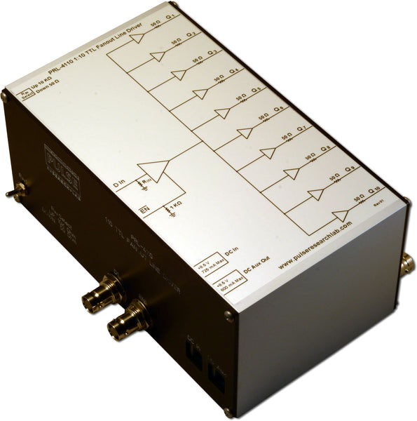
DescriptionThe PRL-4533 is a 1:8 differential fanout buffer system with 8 complementary 50 Ω back-terminated TTL outputs and two inputs. The single-ended TTL input has a selectable 50 Ω or 1 KΩ to ground termination. The Universal Differential input can be driven by LVDS, RS-422, Differential TTL, or Differential ECL signals with source bias. The TTL and Differential inputs are logically ORed; therefore a Hi level applied to either input can be used as a gate signal. The input resistance of the TTL input can be selected to be either 50 Ω or 1 KΩ by a toggle switch. The 1 KΩ input is desirable when interfacing with low power circuits. The TTL input threshold voltage is 1.0 V minimum. When over-driven, the input voltage to the internal circuit is limited to 3.5 V through a current limiting 25 Ω series resistor. The Universal Differential input has a floating 100 Ω termination and requires a minimum differential input swing of 200 mV, with an input Common Mode Range of -2.4 V to +4.0 V. The TTL output swing is typically 0-2.5 V into 50 Ω or 0-5.0 V into high impedance. All outputs are independently buffered, so they can be used single-ended or as a complementary pair, and unused complements or outputs do not require termination. All I/Os are DC coupled, with BNC inputs at the front of the unit and BNC outputs at the rear of the unit. The PRL-4533 is housed in a standard 19-in. rack-mountable enclosure with optional slide rails, powered by an internal auto-switching power supply suitable for 120/240 VAC, 50-60 Hz operation. Models with a suffix, e.g. PRL-4533-C001, indicate a unit with a customer-specific silkscreen or labeling, but all PRL-4533 models are functionally equivalent. (1) A related unit, the PRL-4534, has a true NECL input terminated into 50 Ω/-2 V, and can accept single-ended or differential NECL signals that do not have internal pull-downs. |

Fig. 1A: PRL-4533 Simplified Block Diagram


PRL-4533, Output Side
(0° C ≤ TA≤ 35° C)*
Unless otherwise specified, dynamic measurements are made with all rear-panel outputs terminated into floating 50 Ω.
| SYMBOL | PARAMETER | PRL-4533 | UNIT | Comment | ||
|---|---|---|---|---|---|---|
| Min | Typ | Max | ||||
| RIND | Differential Input Resistance | 95 | 100 | 105 | Ω | |
| RINC | Common Mode Input Resistance | 5 | kΩ | |||
| RT2-1 | Input Resistance, TTL 50 Ω | 49 | 50 | 51 | Ω | |
| RT2-2 | Input Resistance, TTL 1 kΩ | 0.95 | 1.00 | 1.05 | kΩ | |
| VCMV | Input Common Mode Voltage | -2.4 | 4.0 | V | ||
| VIH1 | TTL Input Hi Level | 1.0 | 5.0 | V | Internally limited to 3.5V | |
| VIL1 | TTL Input Lo Level | -0.5 | 0.5 | V | ||
| ROUT | Output Resistance | 49.5 | 50.0 | 50.5 | Ω | Single-ended |
| VOH1 | Output High Level | 2.2 | 2.5 | 2.6 | V | RLOAD = 50 Ω |
| VOH2 | Output High Level | 4.4 | 5.0 | 5.2 | V | RLOAD = 1 MΩ |
| VOL | Output Low Level | -0.25 | 0.00 | 0.25 | V | |
| VVA | AC Input Power | 40 | 45 | VA | ||
| VAC | AC Input Voltage | 108 | 254 | V | ||
| tPROP1 | Prop. Delay to Output ↑, Diff. Input | 6.0 | ns | |||
| tPROP2 | Prop. Delay to Output ↑, TTL Input, 50 Ω | 6.5 | ns | |||
| tR | Rise Time (10%-90%) | 1.4 | 2.0 | ns | See Note 1 | |
| tF | Fall Time (10%-90%) | 1.4 | 2.0 | ns | See Note 1 | |
| tSKEW1 | Ch./Ch. skew between any 2 True Outputs | 500 | ps | |||
| fMAX1 | Max Clock Frequency, Diff. Input | 150 | 175 | MHz | ||
| fMAX2 | Max Clock Frequency, TTL Input | 100 | 125 | MHz | ||
| Size | 19.0”W x 3.5”H x 16.5”D | in | Excluding slide rails | |||
| Weight | 13 | lbs | ||||
Notes:
1. Skew measurements valid when using same input logic level. TTL-input measurements made with TTL input set to 50 Ω.
2. TPROP and TSKEW measurements made via PRL-8508 Test Mux, which provides 50 MHz input clocks in NECL and TTL logic as well as delay-matched NECL and TTL reference timing paths.