Applications:
|
|
Features:
|
|
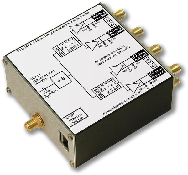
DescriptionThe PRL-255CN is a dual-channel ÷2 and ÷4 frequency divider with DC-coupled, 50 Ω comparator inputs, and complementary NECL outputs. The maximum frequency of operation is greater than 2 GHz, and the minimum input signal required is 10 mVPP at 300 MHz. It is ideally suited for dividing mV sinewave signals or small pulses from laser oscillator photodiodes. The two channels can be cascaded to provide a ÷8 function. The PRL-255CN is an essential lab tool for device test and systems integration in wireless and digital communications applications. The comparator input threshold voltage for the PRL-255CN can be set to +50 mV, 0 V or -50 mV using the common three-position switch provided. It can also be varied independently in each channel by applying a DC bias voltage to one of the two inputs. In this case, a feed through decoupling capacitor of 0.1 µf, such as the PRL-FTC-104, is recommended for preventing false triggering or oscillation if the bias voltage contains varying components, such as noise. Input common mode range is -2.5 V to +4 V. To prevent oscillation in a non-driven channel when the preset threshold is set to 0 V, connect an output to an input so that the two inputs are not at the same voltage. The PRL-255CN is housed in a 1.3 x 2.9 x 3.9-in. enclosure and supplied with a ±8.5 V/1.8 A AC/DC Adapter. |

SPECIFICATIONS (0° C ≤ TA ≤ 35° C)*
| Symbol | Parameter | PRL-255CN | Unit |
Comments |
||
|---|---|---|---|---|---|---|
| Min | Typ | Max | ||||
| RIN | Input Resistance | 49.5 | 50.0 | 50.5 | Ω | |
| VTH+ | Preset Positive Threshold Voltage | +40 | +50 | +60 | mV | |
| VTH- | Preset Negative Threshold Voltage | -60 | -50 | -40 | mV | |
| VTH 0 | Preset Zero Threshold Voltage | -5 | 0 | +5 | mV | |
| VIN Min 1 | Minimum Input Voltage p-p | 10 | 5 | mV | 0 < f < 300 MHz | |
| VIN Min 2 | Minimum Input Voltage p-p | 400 | 200 | mV | 300 MHz < f < 2.5 GHz | |
| IDC | DC Input Current | +35 -310 |
+55 -350 |
mA mA |
||
| VDC | DC Input Voltage | ±7.5 | ±8.5 | ±12 | V | |
| VAC |
AC/DC Adapter Input Voltage |
103 | 115 | 127 | V | |
| tPLH(÷2) |
Propagation Delay to output ↑ |
1.8 | 2.2 | ns | ||
| tPHL(÷2) |
Propagation Delay to output ↓ |
1.8 | 2.2 | ns | ||
| tPLH(÷4) |
Propagation Delay to output ↑ |
2.0 | 2.5 | ns | ||
| tPHL(÷4) |
Propagation Delay to output ↓ |
2.0 | 2.5 | ns | ||
| tr/tf | Rise/Fall Times (20%-80%) | 400 | 600 | ps | Note (1) | |
| tSKEW |
Skew between Q& Q outputs |
50 | 150 | ps | ||
| FMAX | Max clock frequency | 2.0 | 2.5 | GHz | Note (3) | |
| VCMR | Common Mode Range | -2.5 | +4 | V | ||
| Size | 1.3 x 2.9 x 3.9 | in. | ||||
| Shipping weight, incl. AC adapter | 4 | lb. | ||||