Features:
|
|
Applications:
|
|
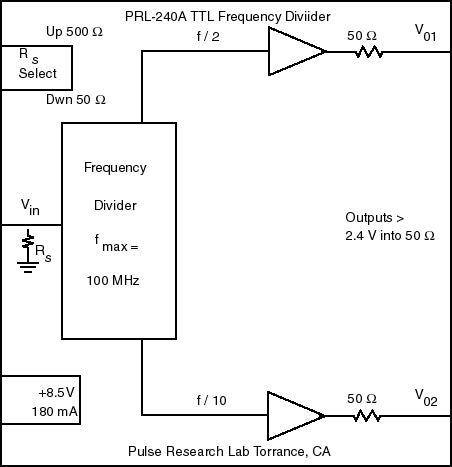
DescriptionThe PRL-240A is a self-contained high-speed TTL frequency divider capable of operating at clock frequencies in excess of 100 MHz. The PRL-240A has ÷2 and ÷10 outputs. The input resistance can be set to 500 Ω or 50 Ω by a toggle switch. A functional block diagram is shown in Fig.1. The back-matched 50 Ω outputs can drive long lines and deliver greater than 2.2 V into 50 Ω loads. The ÷2 output is a square wave, and the ÷10 output has an output pulse positive duty cycle of 40%. The square wave is useful for testing High and Low pass filters. The divider outputs are useful as 'scope triggers for viewing multi-frequency signals. The ÷2 signal is often needed as a control signal for split-cycle timing applications. Each unit is housed in an attractive 1.3 x 2.9 x 2.9-in. extruded aluminum enclosure and has BNC I/O connectors. A ±8.5 V AC/DC Adapter is supplied with each unit. |
Applications:
At power-up all internal counters are in the default state, and the outputs are all low. All output state changes occur on the rising edges of fIN.
- f/2 Output:
- 1st rising edge on the 1st rising edge of fIN.
- 1st falling edge on the 2nd rising edge of fIN.
- 2nd rising edge on the 3rd rising edge of fIN.
- 50% duty cycle (square wave)
- f/10 Output:
- 1st rising edge on the 4th rising edge of fIN.
- 1st falling edge on the 8th rising edge of fIN.
- 2nd rising edge on the 14th rising edge of fIN.
- 40% positive duty cycle

(0° C ≤ TA ≤ 35° C)*
| Symbol | Parameter | Min | Typ | Max | Unit | Comments |
|---|---|---|---|---|---|---|
| RIN (Lo) | Input Resistance | 49.5 | 50.0 | 50.5 | Ω | |
| RIN (Hi) | Input Resistance | 495 | 500 | 505 | Ω | |
| IDC | DC Input Current | 135 | 180 | mA | ||
| VDC | DC Input Voltage | 7.5 | 8.5 | 12.0 | V | |
| VAC1 | AC/DC Adapter Input Voltage, 120 VAC | 103 | 115 | 127 | V | |
| VAC2 | AC/DC Adapter Input Voltage, 220 VAC | 206 | 230 | 254 | V | |
| VIH | Input Hi Level | 2.0 | 2.5 | 5.0 | V | |
| VIL | Input Lo Level | -0.5 | 0.0 | 0.5 | V | |
| VOH1 | Output Hi Level, RLOAD = 50 Ω | 2.2 | 2.5 | V | ||
| VOH2 | Output Hi Level, RLOAD = 1 MΩ | 4.8 | 5.0 | V | ||
| VOL1 | Output Lo Level , RLOAD = 50 Ω | 0.15 | 0.25 | V | ||
| VOL2 | Output Lo Level, RLOAD = 1 MΩ | 0.30 | 0.50 | V | ||
| TPLH | Propagation Delay to f/n↑ output | 10 | 13 | ns | ||
| TPHL | Propagation Delay to f/n↓ output | 10 | 13 | ns | ||
| tr | Rise Time (10%-90%) | 2.0 | 3.0 | ns | ||
| tf | Fall Time (10%-90%) | 1.8 | 3.0 | |||
| TSKEW | Skew between outputs | 1 | 2 | ns | ||
| FMAX | Max clock frequency | 100 | MHz | |||
| Size | 1.3 x 2.9 x 2.9 | in. | ||||
| Shipping weight, incl. AC adapter | 4 | lb. | ||||
*All AC measurements are made with all outputs terminated into 50 Ω