Applications:
|
|||||||||||||||||||||||||
Features:
|
|||||||||||||||||||||||||
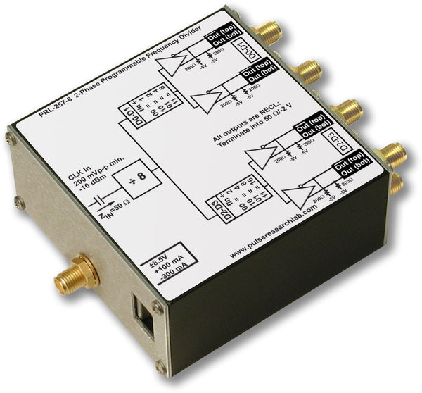
DescriptionThe PRL-260BNT is a DC-coupled, manually programmable, two-phase frequency divider with two sets of divided outputs, Φ1 and Φ2. It is capable of running at input clock frequencies in excess of 1 GHz and outputting divided TTL and NECL clock signals. The input frequency f is first divided down to f/n, where 2 ≤ n ≤ 256, via D1-D8 of a ten-bit DIP switch. The f/n signal is further divided by 1, 2, 4, or 8 for the Φ1 NECL and TTL outputs via D9 and D10, for a maximum ratio of 2048, and by 2, 4, 8 or 16 for the Φ2 NECL output via D11 and D12 of a second two-bit DIP switch, for a maximum ratio of 4096. All outputs are synchronous with the input frequency and are square waves (50% duty cycle), except for Φ1 output when the final divisor is set to 1 (D9-D10=00). When the final divisor is set to 1 the output positive pulse width is equal to the input pulse period. All outputs are complementary and will drive long lines. TTL outputs are back-matched and will drive terminated or unterminated loads. NECL outputs can drive 50 Ω loads terminated into -2 V or AC-coupled 50 Ω loads. A complementary NECL input is logically ORed with a TTL/Small Signal input, enabling the unit to accept TTL input, small signals (≥40 mV), single-ended or differential NECL input, AC-coupled sinewave or other logic inputs. There is an Input Mode switch and a Threshold Voltage switch. For differential NECL inputs, both SMAs are used with both switches up. For single-ended NECL input the lower SMA is used with Input switch down and the Threshold switch up. For AC-coupled input either SMA can be used with both switches up. For TTL input the BNC input is used with the Input switch down and the Threshold switch up. For small signals the BNC input is used with both switches down. The NECL inputs are internally terminated to 50 Ω/-2 V in the differential input mode, and the inverted input to 62 Ω/-1.3 V in the single-ended input mode. The BNC input has a ground-referenced 50 Ω termination, and the minimum signal required is only 0.75 V for TTL (switch up) or 40 mV for small signals (switch down):
The PRL-260BNT is ideal for applications where a frequency divider or prescalar is needed for triggering or down-sampling, and the multiple logic inputs and outputs make it extremely useful in mixed-logic environments. The two phases of output enable applications requiring two different ratios from a common reference frequency. Applications for the PRL-260BNT include data acquisition, test, measurement, R&D, and laser system synchronization. The PRL-260BNT is an improved model of the discontinued PRL-260ANT. It has all the features of the PRL-260ANT plus a small-signal input. The PRL-260BNT is recommended for all new applications. |
|||||||||||||||||||||||||

Typical jitter, as measured on a Tek 11801C Oscilloscope:

Although this is typical performance, this parameter is not tested in Production, nor a guaranteed specification. This scope capture was taken with a previous revision of the product, the PRL-260NT, but the differences between that product and the current revision do not affect jitter.
| Symbol | Parameter | Min | Typ | Max | Unit | Comments |
|---|---|---|---|---|---|---|
| Rin | External Clock Input Resistance | 49.5 | 50.0 | 50.5 | Ω | Except f input in single-ended mode |
| VTT1 | External Clock Input Termination Voltage | -2.2 | -2.0 | -1.8 | V | NECL input |
| VTT2 | External Clock Input Termination Voltage | 0.0 | V | TTL/Small Signal input | ||
| IDC+ | DC Input Current, +8.5 VDC | +165 | +180 | mA | ||
| IDC- | DC Input Current, -8.5 VDC | -790 | -810 | mA | ||
| VDC+ | DC Input Voltage, +8.5 VDC | +7.5 | +8.5 | +12 | V | |
| VDC- | DC Input Voltage, -+8.5 VDC | -12.0 | -8.5 | -7.5 | V | |
| VAC120 | AC/DC Adapter Input Voltage | 103 | 115 | 127 | V | Switched to 120 VAC |
| VAC220 | AC/DC Adapter Input Voltage | 206 | 230 | 254 | V | Switched to 220 VAC |
| VIH1 | External Clock Input Hi Level, NECL |
-1.13 | -0.90 | -0.81 | V | Rin terminated to VTT = -2 V |
| VIH2 | External Clock Input Hi Level, TTL |
0.75 | 0.70 | 3.00 | V | Rin terminated to VTT = 0 V |
| VIH3 | External Clock Input Hi Level, Small Signal |
0.040 | 0.035 | 3.00 | V | Rin terminated to VTT = 0 V |
| VIL1 | External Clock Input Lo Level, NECL |
-1.95 | -1.60 | -1.48 | V | Rin terminated to VTT = -2 V |
| VIL2 | External Clock Input Lo Level, TTL |
-0.50 | 0.00 | 0.50 | V | Rin terminated to VTT = 0 V |
| VIL3 | External Clock Input Lo Level, Small Signal |
-0.50 | 0.00 | 0.01 | V | Rin terminated to VTT = 0 V |
| VOH1 | Output Hi Level @100 MHz, NECL |
-1.13 |
-0.90 |
-0.81 | V | RL terminated to VTT = -2 V |
| VOH2 | Output Hi Level @100 MHz, TTL |
2.00 | 2.20 | V | RL terminated to VTT = 0 V | |
| VOL1 | Output Lo Level @100 MHz, NECL |
-1.95 |
-1.60 |
-1.48 |
V | RL terminated to VTT = -2 V |
| VOL2 | Output Lo Level @100 MHz, TTL |
-0.50 | 0.00 | 0.50 | V | RL terminated to VTT = 0 V |
| tPLH1 | Propagation Delay to f output ↑ | 2500 | ps | From Ext Clk input | ||
| tPLH2 | Propagation Delay to NECL f/n output ↑ | 3750 | ps | From Ext Clk input | ||
| tPLH3 | Propagation Delay to TTL f/n output ↑ | 2500 | ps | From Ext Clk input | ||
| tr/tf1 | Rise/Fall Times (20%-80%), NECL outputs | 600 | 700 | ps | Note (1) | |
| tr/tf2 | Rise/Fall Times (10%-90%), TTL outputs | 1100 | 1350 | ps | ||
| tSKEW1 | Skew ↔ Φ1 NECL outputs | 50 | 150 | ps | ||
| tSKEW2 | Skew ↔ Φ1 TTL outputs | 200 | 400 | ps | ||
| tSKEW3 | Skew ↔ Φ1 NECL and TTL outputs | 1300 | 1600 | ps | ||
| tSKEW4 | Skew ↔ Φ1 and Φ2 NECL outputs | 50 | 150 | ps | n≠1 | |
| fMAX In | Max input clock frequency | 1000 | 1350 | 1500 | MHz | |
| fMAX Out1 | Max output frequency | 500 | 675 | MHz | NECL outputs | |
| fMAX Out2 | Max output frequency | 300 | 350 | MHz | TTL outputs | |
| Size | 1.3 x 2.9 x 6.1 | in. | ||||
| Weight | 10 | Oz | ||||
| Shipping Weight | 4 | lbs | ||||
*All dynamic NECL measurements are made with outputs terminated into 50 Ω/ VTT, using the PRL-550NQ4X, four channel NECL Terminator, connected to a 50 Ω input sampling oscilloscope. TTL outputs are terminated to 50 Ω.
Notes:
(1). The output rise and fall times of each NECL channel are measured with its complementary output terminated into 50 Ω/ VTT. An unused complementary 50 Ω output must be either terminated into 50 Ω/ VTT or AC coupled into a 50 Ω load; otherwise, output waveform distortion and rise time degradation will occur. Use the PRL-ACT-50, Dual Ch. AC-Coupled 50 Ω Termination, for the 50 Ω/VTT termination. Use the PRL-SC-104 or PRL-ACX-12dB (0.1 µf DC block and 12 dB AC-coupled attenuator, respectively) for connection of NECL signals to 50 Ω input oscilloscopes.