Applications:
|
|
Features:
|
|
DescriptionThe PRL-350RS is a ready-to-use, high-speed, dual-channel comparator module with RS-422 outputs. The PRL-350RS has a typical maximum clock frequency in excess of 500 MHz and has differential RS-422 outputs designed for driving floating 124 Ω transmission lines. The PRL-350RS has DC-coupled 50 Ω inputs and differential 124 Ω outputs. The input threshold voltage can be selected either from a set of preset values of +50 mV, 0 V or -50 mV using a common three-position switch, or varied independently for each channel by applying a DC bias voltage to one of the two inputs. The input Common Mode Range is -2.0 V to +3.0 V. The input threshold voltage can also be varied independently in each channel by applying an external DC bias voltage or shunt resistor to the D input.
These high-speed comparators are Mini Modular Instruments™ that can be used as peak detectors, threshold detectors, sinewave-to-square wave converters, window comparators or differential line receivers, etc. The typical minimum input voltage of 10 mVPP is required for up to 100 MHz. It is recommended that the non-driven input be terminated into 50 Ω when the input frequency is near fMAX and its amplitude is less than 20 mVPP. The PRL-350RS model has SMA input and output connectors. The PRL-350RSTR has SMA inputs and Triax output connectors. Each unit is supplied with a ±8.5 V AC/DC Adapter and housed in a 1.3 x 2.9 x 3.9-in. extruded aluminum enclosure |

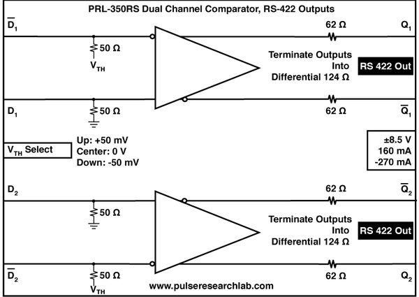 Fig. 1D PRL-350RS Block Diagram
 Fig. 1E PRL-350RSTR Block Diagram
Anritsu Application Note for PON Module Testing with Anritsu MP1800A
Signal Quality Analyzer and PRL-350 Series Comparators (1.1 MB PDF)
BERT Level Translation
Anritsu engineers and customers around the world rely on our PRL-350 Series comparators for level conversion when testing Passive Optical Network (PON) modules.
PON module testing often requires converting the -1.0 to 0 V signals output by the MU181020A Pulse Pattern Generator cards to the LVTTL, PECL or LVPECL levels required by many ONU and OLT modules, typically for the Data, Pre-bias, and Reset signals.
Popular models include:
- PRL-350TTL, Dual Channel Comparator with TTL Outputs
- PRL-350LP, Dual Channel Comparator with LVPECL Outputs
- PRL-350P, Dual Channel Comparator with PECL Outputs
App Note and block diagram copyright and courtesy of Anritsu Corporation.
(0° C ≤ TA ≤ 35° C)*
Unless otherwise specified, dynamic measurements are made with all outputs terminated into 50 Ω/VTT, where VTT = +3 V for PECL outputs.
| Symbol | Parameter | PRL-350RS | Unit | ||
|---|---|---|---|---|---|
| Min | Typ | Max | |||
| RIN | Input Resistance | 49.5 | 50 | 50.5 | Ω |
| ROUT | Output Resistance | 123 | 124 | 125 | Ω |
| VTH+ | Preset positive threshold voltage | 45 | 50 | 55 | mV |
| VTH- | Preset negative threshold voltage | -55 | -50 | -45 | mV |
| VTH0 | Preset zero threshold voltage(1) | -10 | 0 | 10 | mV |
| VOLNL | Output Low Level, No Load | -1.2 | -1.0 | -0.8 | V |
| VOLFL | Output Low Level, 124 Ω Load | -0.2 | 0 | 0.2 | V |
| VOHNL | Output High Level, No Load | 2.75 | 3.0 | 3.3 | V |
| VOHFL | Output High Level, 124 Ω Load | 1.8 | 2.0 | 2.2 | V |
| IDC1 | DC Input Current, +8.5 V | 165 | 175 | mA | |
| IDC2 | DC Input Current, -8.5 V | -235 | -250 | mA | |
| VDC | DC Input Voltage | ±7.5 | ±8.5 | ±12 | V |
| VAC | AC/DC Adapter Input Voltage | 103 | 115 | 127 | V |
| tPLH | Propagation Delay to output↑ | 2 | ns | ||
| tPHL | Propagation Delay to output↓ | 2 | ns | ||
| tr/tf | Rise/Fall Times(2) | 1100 | 1250 | ps | |
| tSKEW | Skew between any 2 outputs | 200 | 400 | ps | |
| Vin I | Minimum Input Voltage @ 150 MHz(1) | 20 | 10 | mVPP | |
| Vin II | Minimum Input Voltage @ 250 MHz(1) | 40 | 20 | mVPP | |
| VCM | Input Common Mode Range | -2.0 | +3.0 | V | |
| fmax | Max. Clock Frequency | 500 | 550 | MHz | |
| Size | 1.3 x 2.9 x 3.9 | in. | |||
| Weight, w/o AC adapter | 7 | Oz | |||
| Shipping weight, w/AC adapter | 4 | lb | |||
(1) If the switch is set to the center position (0 V threshold) a non-driven channel will oscillate and induce jitter in the driven channel. Connect any output to any input to stop the oscillation.
(2) 10%-90% for RS-422.

While we believe these models to be accurate, no representations are made as to accuracy or suitability for any application:
PRL-350RS: