Applications:
|
|
Features:
|
|
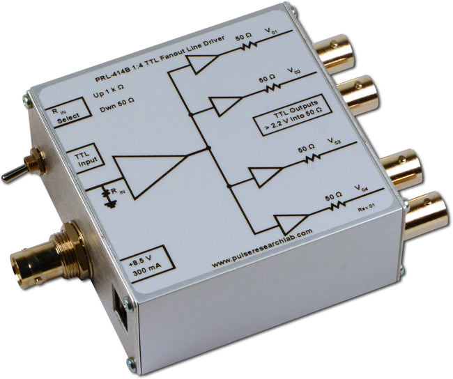
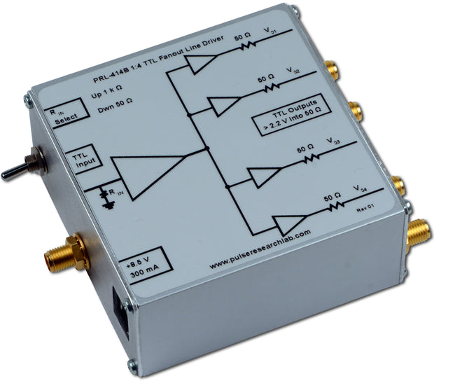
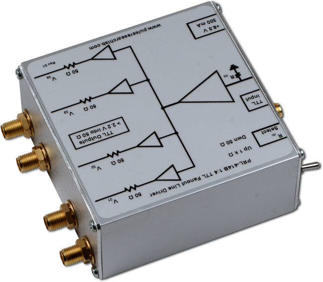
DescriptionThe PRL-414B is a 1:4 fanout 50 Ω TTL Line Driver/Pulse Distribution Amplifier. It is intended for distribution of high-speed clock and logic signals to multiple loads via long lines. The 50 Ω back-terminated outputs can drive long lines with or without 50 Ω load terminations; With 50 Ω load terminations, however, all outputs of the PRL-414B can drive 100 ft of 50 Ω cables at clock rates greater than 80 MHz. In one important application, the PRL-414B is used for distributing a precision clock signal to a number of test stations in the lab. The input resistance of the PRL-414B can be selected to be either 50 Ω or 1 kΩ by a switch. The 1 kΩ-input is desirable when interfacing with low power circuits. All I/Os are DC coupled and have BNC or SMA connectors. The PRL-414B is housed in a 1.3 x 2.9 x 2.9-in. extruded aluminum enclosure and is supplied with a ±8.5 V/±1.8 A AC/DC Adapter. A maximum of four units can share a single AC/DC adapter using the PRL-730 voltage distribution module. If mounting is needed, a pair of the #35001420 mounting brackets can accommodate any two PRL modules of the same length. A block diagram showing the equivalent input and output circuits of the PRL-414B is shown in Fig. 1. |

Fig. PRL-414B Block Diagram

Application Notes:
Driving the input of the PRL-414B with a sine wave:

Related Products for PRL-414B
- PRL-171, Fanout Crystal Clock Source
- PRL-172, Four-Phase Crystal Clock Source (f, f/2, f/4, f/8)
- PRL-173, Two-Phase Crystal Clock Source (f, f/5)
- PRL-852A, 2 GHz A/B Switch
- PRL-220A, Four Phase Frequency Divider (f/2, f/4, f/8, f/16)
- PRL-240A, Two Phase Frequency Divider (f/2, f/10)
Comparators/Sinewave Convertors
- PRL-350TTL Dual Channel Output Comparators
- PRL-420ND Dual Channel TTL to ECL Translator
- PRL-420PD Dual Channel TTL to PECL Translator
- PRL-420TD Dual Channel Differential TTL Line Driver (converts single-ended TTL to differential TTL)
- PRL-450ND Dual Channel ECL to TTL Translators
- PRL-450PD Dual Channel PECL to TTL Translators
PRL-470 High Speed Line Driver and Level Translator
- Mounting Brackets
- Extra AC/DC Adapters (one included with unit)
- Voltage Distribution Modules, for sharing AC adapters among several modules
- Cables
SPECIFICATIONS (0° C ≤ TA ≤ 35° C)*
| Symbol | Parameter | Min | Typ | Max | Unit | Comments |
|---|---|---|---|---|---|---|
| RIN LO | Input Resistance Low Range | 49.5 | 50 | 50.5 | Ω | |
| RIN HI | Input Resistance High Range | 990 | 1000 | 1010 | Ω | |
| ROUT | Output Resistance | 50 | Ω | |||
| VIL | TTL Input Low Level | -0.5 | 0 | 0.5 | V | |
| VIH | TTL Input High Level | 2.0 | 2.4 | 5.0 | V | |
| VOL | TTL Output Low Level | 0 | 0.25 | 0.5 | V | RL=50 Ω |
| VOH1 | TTL Output High Level | 2.2 | 2.5 | V | RL=50 Ω @ DC | |
| VOH2 | TTL Output High Level | 4.4 | 5 | V | RL=1 MΩ @ DC | |
| IDC1 | DC Input Currents | 280 | 350 | mA | f ≤ 100 MHz | |
| IDC2 | DC Input Currents | 220 | 250 | mA | f =50 MHz sq. wave(1) | |
| VDC | DC Input Voltages | 7.5 | 8.5 | 12 | V | |
| VAC | AC/DC Adapter Input Voltage | 103 | 115 | 127 | V | |
| TPLH | Propagation Delay to output ↑ | 10 | 12 | ns | ||
| TPHL | Propagation Delay to output ↓ | 8 | 12 | ns | ||
| tr | Rise Time (10%-90%) | 2.2 | 3 | ns | f =50 MHz sq. wave | |
| tf | Fall Time (10%-90%) | 1.8 | 3 | ns | f =50 MHz sq. wave | |
| TSKEW | Skew between any 2 outputs | 500 | 1500 | ps | f =50 MHz sq. wave | |
| FMAX1 | Max. Clock Frequency(2) | 100 | 120 | MHz | RG58C/U Cable length =3 ft | |
| FMAX2 | Max. Clock Frequency(3) | 80 | RG58C/U Cable length =100 ft | |||
| PWMIN | Min. Pulse Width | 4 | ns | ↑ Input | ||
| PWMIN | Min. Pulse Width | 6 | ns | ↓ Input | ||
| Size | 1.3 x 2.9 x 2.9 | in | ||||
| Weight | 5 | Oz | Excluding AC adapter | |||
| Shipping Weight | 4 | lb | Including AC adapter | |||
Unless otherwise specified, dynamic measurements are made with all outputs terminated into 50 Ω.
Notes:
(1) For sharing a single PRL-760E, ±8.5 V ±1.8 A AC/DC adapter, the total current should not exceed 1.8 A.
(2) fMAX should not exceed 120 MHz; otherwise, damage of the unit due to overheating may result.
(3) fMAX2 is measured by connecting a second PRL-414B at the end of the 100 ft. cable.

While we believe these models to be accurate, no representations are made as to accuracy or suitability for any application:
PRL-414B (BNC I/Os):

PRL-414B-SMA (SMA I/Os):