Applications:
|
|
Features:
|
|
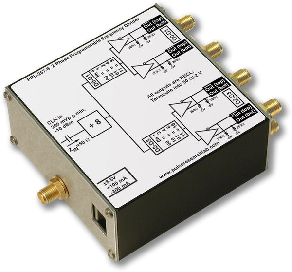
DescriptionThe PRL-170N is a ready-to-use NECL crystal clock source module with differential outputs suitable for driving 50 Ω loads terminated to -2 V or AC-coupled 50 Ω loads. Standard crystal frequencies provided are 50 MHz, 100 MHz, 200 MHz, 400 MHz, 500 MHz and 622.08 MHz. Other crystal frequencies are also available. The PRL-170N is an essential laboratory tool in applications where a precision and low jitter high frequency clock source is required. Model number designation is PRL-170N-xxx, where "xxx" represents the user specified clock frequency in MHz, such as 200 or 622, etc. The PRL-170N is housed in a 1.3 x 2.9 x 2.2-in. extruded aluminum enclosure and supplied with a ±8.5 V AC/DC adapter. |

PRL-170N Block Diagram
(0° C ≤ TA ≤ 35° C)*
| Symbol | Parameter | PRL-170N | Unit | Comments | ||
|---|---|---|---|---|---|---|
| Min | Typ | Max | ||||
| VOL | Output Low Level | -1.95 | -1.70 | -1.48 | V | |
| VOH | Output High Level | -1.13 | -0.90 | -0.81 | V | |
| IDC | DC Input Current | -300 | -200 | mA | Xtal freq. dependent | |
| VDC | DC Input Voltage | -12 | -8.5 | -7.5 | V | |
| VAC | AC/DC Adapter Input Voltage | 103 | 115 | 127 | V | |
| tr/tf | Rise/Fall Times (20%-80%), f, f outputs | 500 | 650 | ps | Note (1) | |
| tSKEW1 | Skew between f and f outputs | 20 | 75 | ps | ||
| fMAX | Max crystal clock frequency | 825 | MHz | Note (2) | ||
| ∆f | Frequency Stability | 100 | ppm | |||
| Frequency Jitter | 20 | ps | ||||
| Positive Duty Cycle | 50 | 40 | % | |||
| Size | 1.3 x 2.9 x 2.2 | in. | ||||
| Weight excl. AC adapter | 5 | Oz | ||||
| Shipping weight incl. AC adapter | 4 | lb. | ||||