Features:
|
|
Applicatios:
|
|
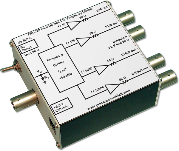
DescriptionThe PRL-230 is a four-decade TTL frequency divider capable of operating at clock frequencies in excess of 100 MHz. It has ÷10, ÷100, ÷1000 and ÷10,000 division ratios with 50 Ω outputs, each capable of delivering greater than 2.2 V into a 50 Ω load. Except for the ÷10 channel, all others have square wave outputs (50% duty cycle). For the ÷10 channel, the output pulse width is equal to the period (1/f) of the input signal. The PRL-230 is ideally suited for applications that require very large division ratios, and the square wave outputs are useful for testing High-pass and Low-pass filters. When used together with the PRL-260BNT programmable frequency divider, they can generate divided signals from 1.2 GHz down to 29 Hz. Multiple units can be cascaded for even further division. The input resistance of the PRL-230 can be set to 500 Ω or 50 Ω by a toggle switch. The back-matched 50 Ω outputs of this frequency divider can drive long lines with or without 50 Ω terminations. A functional block diagram of the unit is shown in Fig. 1. The PRL-230 is housed in a 1.3 x 2.9 x 2.9-in. extruded aluminum enclosure. The PRL-230-BNC has BNC I/O connectors, and the PRL-230-SMA has SMA I/O connectors. A ±8.5 V AC/DC adapter is included. If mounting is desired, a pair of 35001420 mounting brackets can accommodate two PRL modules of the same length. A number of PRL modules can also share a single ±8.5 V AC/DC adaptor using the PRL-730 voltage distribution module. Please see the Accessories Section for more detail. |

Applications:
At power-up all internal counters are in the default state, and the outputs are all low. All output state changes occur on the rising edges of fIN.
- f/10 Output:
- 1st rising edge on 4th rising edge of fIN.
- 1st falling edge on 8th rising edge of fIN.
- 2nd rising edge on 14th rising edge of fIN.
- 2nd falling edge on 18 rising edge of fIN.
- 40% positive duty cycle
- f/100 Output:
- 1st rising edge on 5th falling edge of f/10
- 1st falling edge on 10th falling edge of f/10
- 2nd rising edge on 15th falling edge of f/10
- 50% duty cycle
- f/1000 Output:
- 1st rising edge on 5th falling edge of f/100
- 1st falling edge on 10th falling edge of f/100
- 2nd rising edge on 15th falling edge of f/100
- 50% duty cycle
- f/10000 Output:
- 1st rising edge on 5th falling edge of f/1000
- 1st falling edge on 10th falling edge of f/1000
- 2nd rising edge on 15th falling edge of f/1000
- 50% duty cycle

(0° C ≤ TA ≤ 35° C)*
| Symbol | Parameter | Min | Typ | Max | Unit | Comments |
|---|---|---|---|---|---|---|
| RIN1 | Input Resistance, 50 Ω | 49.5 | 50.0 | 50.5 | Ω | |
| RIN2 | Input Resistance, 500 Ω | 495 | 500 | 505 | Ω | |
| IDC | DC Input Current | 175 | 200 | mA | ||
| VDC | DC Input Voltage | 7.5 | 8.5 | 12 | V | |
| VAC | AC/DC Adapter Input Voltage | 103 | 115 | 127 | V | |
| VIH | Input Hi Level | 2.0 | 2.2 | 5.0 | V | |
| VIL | Input Lo Level | -0.5 | 0.0 | 0.5 | V | |
| VOHNL | Output Hi Level, No load | 4.8 | 5.0 | V | RL=1 MΩ | |
| VOHFL | Output Hi Level, Full load | 2.2 | 2.5 | V | RL=50 Ω | |
| VOLNL | Output Lo Level, No load | 0.30 | 0.50 | V | RL=1 MΩ | |
| VOLFL | Output Lo Level, Full load | 0.15 | 0.25 | V | RL=50 Ω | |
| TPLH/TPHL | Propagation Delay to f/10 output | 4 | 8 | ns | ||
| TPLH/TPHL | Propagation Delay to f/100 output | 15 | 30 | ns | ||
| TPLH/TPHL | Propagation Delay to f/1k output | 30 | ns | |||
| TPLH/TPHL | Propagation Delay to f/10k output | 60 | ns | |||
| tr | Rise Time (10%-90%) | 2.0 | 3.0 | ns | ||
| tf | Fall Time (10%-90%) | 1.8 | 3.0 | ns | ||
| fMAX | Max clock frequency | 100 | 125 | MHz | RIN = 50 Ω | |
| Size | 1.3 x 2.9 x 2.9 | in. | ||||
| Weight | 5 | oz. | ||||
| Shipping weight, incl. AC adapter | 4 | lb. | ||||

